BASIC INFO
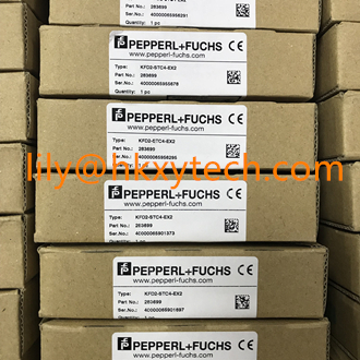
Pepperl + Fuchs KCD2-STC-Ex1.ES SMART Transmitter Power Supply Isolated Barrier
Features
• 1-channel isolated barrier
• 24 V DC supply (Power Rail)
• Input for 2-wire SMART transmitters and current sources
• Output for 4 mA ... 20 mA or 1 V ... 5 V
• Sink or source mode
• Line fault detection (LFD)
• Housing width 12.5 mm
• Up to SIL3 acc. to IEC 61508
Function
This isolated barrier is used for intrinsic safety applications.
The device supplies 2-wire transmitters in the hazardous area,
and can also be used with current sources.
It transfers the analog input signal to the safe area as an
isolated current value.
Bi-directional communication is supported for
SMART transmitters that use current modulation to transmit
data and voltage modulation to receive data.
The output is selected as a current source, current sink, or
voltage source via DIP switches.
A fault is signalized by LEDs acc. to NAMUR NE44 and a
separate collective error message output.
Test sockets for the connection of HART communicators are
integrated into the terminals of the device.
Application
The device supports the following SMART protocol:
• HART
General specifications
Signal type Analog input
Functional safety related parameters
Safety Integrity Level (SIL) SIL 3
Supply
Connection Power Rail or terminals 9+, 10-
Rated voltage Ur 19 ... 30 V DC
Ripple ≤ 10 %
Rated current Ir ≤ 50 mA
Power dissipation ≤ 800 mW
Power consumption ≤ 1.2 W
Input
Connection side field side
Connection terminals 1+, 2-; 3+, 4-
Input signal 4 ... 20 mA , limited to approx. 27 mA reverse polarity protected
Line fault detection downscaling ≤ 3 mA ; upscaling ≥ 22 mA
Voltage drop approx. 5 V on terminals 3+, 4-
Available voltage ≥ 15 V at 20 mA terminals 1+, 2-
Output
Connection side control side
Connection terminals 5-, 6+
Load 0 ... 300 Ω (source mode)
Output signal 4 ... 20 mA or 1 ... 5 V (on 250 Ω, 0.1 % internal shunt)
4 ... 20 mA (sink mode), operating voltage 16 ... 28 V
Ripple 20 mV rms
Fault indication output
Output type fault bus signal , open collector transistor
Transfer characteristics
Deviation at 20 °C (68 °F)
≤ ± 20 µA incl. calibration, linearity, hysteresis, loads and supply voltage fluctuations (source mode and sink
mode 4 ... 20 mA)
≤ 10 mV incl. calibration, linearity, hysteresis and fluctuations of supply voltage (source mode 1 ... 5 V)
Influence of ambient temperature < 2 µA/K (0 ... 70 °C (32 ... 158 °F)); < 4 µA/K (-20 ... 0 °C (-4 ... 32 °F)) (source mode and sink mode 4 ... 20
mA)
< 0.5 mV/K (0 ... 70 °C (32 ... 158 °F)); < 1 mV/K (-20 ... 0 °C (-4 ... 32 °F)) (source mode 1 ... 5 V)
Frequency range field side into the control side: bandwidth with 1 mApp signal 0 ... 3 kHz (-3 dB)
control side into the field side: bandwidth with 0.5 Vpp signal 0 ... 3 kHz (-3 dB)
Settling time ≤ 200 ms
Rise time/fall time ≤ 20 ms
Galvanic isolation
Input/Output safe electrical isolation acc. to IEC/EN 60079-11, voltage peak value 375 V
Input/power supply safe electrical isolation acc. to IEC/EN 60079-11, voltage peak value 375 V
Output/power supply Basic isolation acc. to EN 61010-1 rated insulation voltage ≤ 50 V
Indicators/settings
Display elements LEDs
Control elements DIP-switch
Configuration via DIP switches
Labeling space for labeling at the front
Directive conformity
Electromagnetic compatibility
Directive 2014/30/EU EN 61326-1:2013 (industrial locations)
Conformity
Electromagnetic compatibility NE 21:2006
Degree of protection IEC 60529:2001
Ambient conditions
Ambient temperature -20 ... 70 °C (-4 ... 158 °F)
Mechanical specifications
Degree of protection IP20
Connection screw terminals
Mass approx. 100 g
Dimensions 12.5 x 114 x 124 mm (0.5 x 4.5 x 4.9 inch) , housing type A2
Mounting on 35 mm DIN mounting rail acc. to EN 60715:2001
Data for application in connection
with hazardous areas
EU-Type Examination Certificate CESI 10 ATEX 071
KCD2-STC-Ex1
KCD2-STC-Ex1.ES
KFD2-CRG2-Ex1.D
KFD2-HLC-Ex1.D
KFD2-HLC-Ex1.D.2W
KFD2-STC4-Ex1
KFD2-STC4-Ex1.2O
KFD2-STC4-Ex1.2O.H
KFD2-STC4-Ex1.H
KFD2-STC4-Ex2
KFU8-CRG2-Ex1.D
KCD2-STC-Ex1.2O
KCD2-STC-Ex1.2O.ES
KCD2-STC-Ex1.ES.SP
KCD2-STC-Ex1.SP
KFD2-STC3-Ex1
KFD2-STC4-Ex1-Y1
KFD2-STC4-Ex1.2O-Y1
KFD2-STC4-Ex1.ES
KFD2-STC4-Ex2-Y1
KFD2-STC5-Ex1
KFD2-STC5-Ex1.2O
KFD2-STC5-Ex1.2O.H
KFD2-STC5-Ex1.H
KFD2-STC5-Ex2
KFD2-STC5-Ex2
KFD2-STC5-Ex2
KFD2-STV4-Ex1.2O-1
KFD2-STV4-Ex2-1
KFD2-STV4-Ex2-2
KFD2-STV5-Ex1-1
KCD2-STC-Ex1.2O.DE
KFD2-HLC-Ex1.D.4S
KFD2-STV4-Ex1.2O-2
KCD2-STC-Ex1.HC
KCD2-STC-Ex1.HC.SP
KFD2-STC4-Ex1
KFD2-STC4-Ex1-Y1
KFD2-STC4-Ex1.2O
KFD2-STC4-Ex1.2O-Y1
KFD2-STC4-Ex1.2O.H
KFD2-STC4-Ex1.H
KFD2-STV4-Ex1-1
KFD2-STV4-Ex1-2
KFD2-STV4-Ex1.2O-1
KFD2-STV4-Ex2-1
KFD2-STV4-Ex2-2
KFD2-STV4-Ex1.2O-2
KFD2-STC3-Ex1
KCD2-STC-Ex1-Y1
-----------------------------------
Lily
HONGKONG XIEYUAN TECH CO., LIMITED
T: 86-027-85581877 F: 86-027-85309780
Mail:lily@whxyauto.com
Ad: 7-A16,Caishen Commercial Plaza,Hankou Railway Station,Wuhan, Hubei, China
Web: www.hkxytech.com


